Step 5
 Tools Required:
- Metric spanners
- Allen Keys
- Metric sockets
- Files
- Drill
- Counter sinker
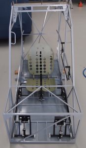
Step 5 is when the toe brakes were fitted to the rudder pedals (rear toe brakes optional)
This step is basic to follow in the manual and as in previous steps, we wanted these components painted before we continued so parts were fitted, removed and then painted before final instillation.
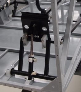
The only real snags we had during this step was the fitting of the slave cylinders and the drilling of some holes in the lower part of the toe pedals. The cylinders needed a slight file to fit in their correct position and still be able to rotate. The orientation is important on these cylinders so attention was paid to have them set up correctly. This is all clearly marked in the construction manual.
Some of the holes for the nylon blocks that guide the toe pedals needed to be drilled and counter sunk to make the hardware fit flush.
Front toe brakes and master cylinder
But on the whole this step is pretty well explained in the manual
The toe pedals on the Groppo trail are adjustable with 3 different holes on the rear where it attaches to the ram on the slave cylinder. Bear this in mind during the testing phase of the build in case you’re uncomfortable with the positioning and or need some extra clearance.
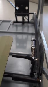
Again, all the hardware in this step was installed, measured and then cut to a desired length.
Once all this was achieved, we removed the parts and alodined them, prepped and painted them and they were finally installed with a desired friction set.
Then, the beginnings of the brake lines were installed simply because it is much easier to access the pedals from both the front and sides at this stage of the build.
So, tubing was measured and installed to the slave cylinders with the correct fittings before it was then coiled up and tucked out of harm’s way.
Rear toe brake and master cylinder
Recent Comments