Required Equipment- (aside from basic hand tools)
- Drill and metric drill bits
- Sandpaper and/or linisher
- Rivnut insertion tool
In the construction manual, Step 1 involves fitting some of the aileron controls. This step is a little preemptive, as will be seen in later steps, because the hardware used to secure the self-aligning bearings on the upper control rod have to be removed when fitting the roof panel. There are also a few other tasks later on that are a lot easier to accomplish with these controls removed.
Having said this, there is no harm in doing a “dry” fit just to make sure everything lines up and goes together as advertised.
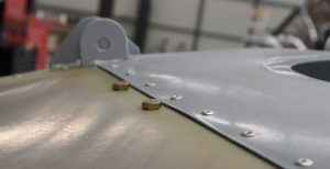
Seen here are the bolts used to fasten the a self aligning bearing to the frame. Note how the bolt heads have to go through the roof skin.
Now there are going to be a few holes on the frame that are “bulked” up with the powder coat and need clearing out with the correct sized drill, you could go through and clear all the holes that you believe need to be done or you could do it as we did, and just clear them as you go.
Once a hole has been cleared of excess paint, it is likely that the inside of the hole is now bare metal and thus should have some kind of protection against the environment. We just used a bit of thyxo #2 aviation grease on the hardware as we installed it to provide this protection.
One of the first things we noticed that wasn’t just a straightforward fit was the aileron idler arm on the upper right of the cockpit frame. The idler arm nylon bushing seemed to be manufactured with an outside diameter slightly too large. This combined with the buildup of paint in the tube the bushing is to be installed meant that there was no way it was going to fit where it was supposed to without some degree of sanding. Using a small sanding drum off a Dremel, or similar, is a quick and easy way to get rid of the paint in mounting tube and by attaching the bushing to a drill press, running it on a low speed and using sandpaper ( not too coarse ), we were quickly able to reduce the outside diameter for a perfect fit.
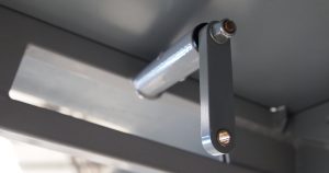
Aileron control idler arm
The second thing in Step 1 that needed a bit of attention was the aileron control (lower) torque tube that runs under the seats, it also pivots on nylon bushings. The upper bushing on the front set seemed to thick to fit inside the retaining lip and both forward and aft bushing inside diameter seemed to clamp the tube too tight. The collective result being that aileron control movements were to stiff even before any linkages were connected. Again for the forward (upper) bushing, a small amount of sanding was required to make it a bit thinner ( a linisher made it a quick process). As for the bushings clamping the tube too tight, rather than sand this out, we opted to pack the bushings apart slightly using thin aluminium washers.
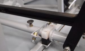
Aft elevator mechanical stop and aileron torque tube pivot bushes
Now before we leave this control tube, there was one other task that needed to be done and that was the drilling of the aft elevator stop. In the construction manual, it suggests that there is a hole already drilled for the rivnut that is to facilitate the mounting for the aft aileron stop… This was not the case in our kit. Furthermore, there are no dimensions for where this hole needs to be drilled so at this point it pays to dry fit the forward control stick (refer to Step 2) to get an idea of how far back the aft stop should be.
Once that has been determined, you will need to drill a hole as close to the centerline of the tube (in line with the forward stop) as possible. This is a little more difficult to get precise, as the drill tends to wander on a curved surface. It is no big deal if it is slightly off skew but try to get it as close as possible.
When fitting the rivnuts, we opted to install them wet primed rather than using grease as you don’t want these little babies to move once they have been squeezed up. Once the rivnuts for the control stops have been installed, you can just wind in the stop hardware by hand at this point so they don’t go walk about.
The last item on this control tube that needs a little attention is the 2 brass bushings that the control sticks pivot fore and aft on. The holes they need to fit into just need a bit of the paint taking out so they fit snugly (not jammed in tight) and it is important to note that if something does not feel like it fits well, forcing it in too far will most likely cause you problems as it is probably going to get jammed part way in and it will be difficult to get all the way in or back out again so it is important to make sure everything feels like it “wants” to go together before trying to force it.
The upper aileron control tube with associated self-aligning bearings fitted up nicely with no hassle.
All these pieces need to stay in place until steps 2 and 3 have been completed.
Happy Building…
Recent Comments