Required Equipment
- metric spanners/ sockets
- files
- nylon/rubber mallet
- pneumatic rotary burr
- de-burring tool
In the Groppo Trail Construction Manual (GTCM), Step 2 covers the assembly and installation of the flight control sticks. This includes both sticks and connecting rods. Similar to Step 1, Step 2 is also a little preemptive simply because there is a great deal of work to be done in the cockpit in later steps and if the control sticks are permanently installed, they become a hinderance to work around. This being said, they are very simple to fit and remove so spend the time to get it right and then remove them and put them aside until you are ready for them to go in permanently.
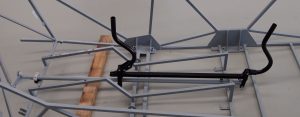
We had similar issues with this step as we did in Step 1. Nothing major but just a bit of tweaking and fine tuning to get the parts to go together nicely. The first issue we encountered was the mounting arms of the two control sticks were not spread far enough apart. Some manipulation with a shifter (monkey wrench) or parallel jaw multi grips will do the trick. Our other hurdle with the control sticks was with the forward control stick binding on the elevator push-pull rod that connects the two sticks together (G000459). This binding occured where the control stick tube ended and the mounting arms attached, preventing the forward mechanical stop from making contact. Using a rotary burr, we scalloped out the bottom side of the tube to prevent binding and also give adequate room to allow for wiring to be run up the stick for comms, trim and flap switches etc.
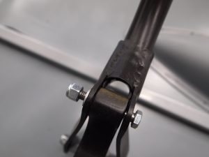
Forward control stick attachment
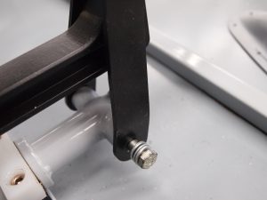
Forward control stick attachment
Our only other problem with Step 2 was a nylon bushing that guides the connecting rod that connects the control sticks to the elevator push-pull tubes in the tail section. This bushing was a little too tight on the tube and didn’t allow for it to slide freely. To rectify, we cleared it with a file and lubricated it with some Thyxo #2 aviation grease.
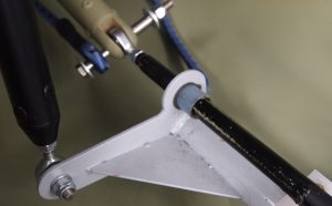
Nylon bushing for elevator connecting rod guide
Some important things to consider when dry fitting parts is the hardware. In this step, a lot of the hardware used for the permanent fitment of the controls have Nyloc nuts. Once a Nylon nut is fitted, if you undo it, it will lose some of its locking ability and the more you put in on and off, the less it will lock. Being that we are dealing with flight controls here, it is very important to ensure the hardware used for final fitment is new and has maximum locking ability. The easiest way to ensure this is to use plain nuts during the dry fit stage and only use the Nylocs for final fitment.
Another thing to keep in mind when doing your dry fit is the tolerances with paint. As an example, if you hone out a bushing to fit perfectly to a tube when it is bare metal, a few thousandths of an inch of paint will make the fit not so perfect anymore. Now you may or may not choose to paint your flight controls, but if you don’t, you risk dissimilar metal corrosion as some parts are aluminium and some are stainless steel and some chromoly. Our recommendation is to paint all parts. Painted parts are also easier to inspect for damage so there is no real argument for not painting parts.
So once you have ironed out any issues and you have completed a dry assembly according to the GTCM, if you’re happy with its movement range and friction, it is time to remove these parts and prepare for alodine and paint.
One thing that you may notice when assembling is that all the bolts allocated to the construction seem much too long, this is not the case! If you look closely at the load bearing portion of the bolt you will notice that it is shanked. It is this shank length that is important not the overall length of the bolt.
Some of the instructions call for more than one washer under the nut. This is simply to make sure the nut doesn’t become thread bound on the shank of the bolt.
Needless to say, if you are inclined as we were, cut the excess thread off each bolt to reduce overall weight, improve aesthetics and prevent your trousers getting snagged on them, however, it is important to make sure you have a MINIMUM of 1-3 threads protruding past the nylon section of the nut when it tightened to the correct torque value.
Happy building…….
Recent Comments