Step 4
Required Equipment
- Metric spanners
- Allen keys
- Metric sockets
- Files
- Rivnut tool
Step 4 entails the assembly and installation of the rudder control pedals. This step is quite a basic step but did require some very minor modification to some of the parts, provided with the kit, to facilitate correct alignment and smooth operation of the pedals.
Given the finish quality of the supplied rudder pedals, and the look we want to achieve on our build, we decided to paint our pedals before final assembly but this is purely optional.
The first thing to do is gather all your parts and hardware together as listed in the GTCM. If you have a kit with rear brakes, you will find that they have provided an extra set of push-pull tubes that connect the front pedals to the rear. The tube you will need to use with rear brakes is a lot bigger than the one used for aircraft without rear brakes. This is to facilitate the mounting of the brake cylinders for the rear brakes.
Once you have all parts identified and accounted for, it is time to assemble them loosely and offer them up to the airframe. At this point you will notice that the nylon bushing blocks, that secure the rear pedals and allow them to pivot, foul on the seam weld that attaches their mounting plates to the frame. To overcome this, we used the linisher to put a bevel on the edge that fouled on the weld and it was crisis averted.
You will also notice that, as in previous steps, the hardware provided seems to be far too long, but again, it is the length of the shank that matters so you will just have to trim excess off ensuring a minimum of 1-3 threads protruding through the nylon locking portion of the nut. If you are using plain nuts for the dry assembly, do not cut the threads using a plain nut as your reference or you will cut your bolt too short. The nylon nuts are deeper than a plain nut.
When assembling and fitting the push-pull tubes between front and rear, you will find a threaded rod end is to be fitted in the front end of the tube. There is no nominal length given in the GTCM for these. We basically took midway as a good starting point. When final rigging is done, they may have to be adjusted but that should not big a big issue. Making sure that once the rod ends are installed, that both tubes, including rod end, are identical length to ensure there is no bias on either pedal.
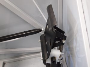
Pedal painted and installed
The mechanical stop for the pedals is on the rear pedals by way of a rivnut and bolt. There is no real instruction on where this rivnut is to be installed in the GTCM but careful study of the photographs provided with the GTCM revealed where they are required. Whilst the rivnut can be installed, the stop distance is not determined until rigging in later stages of the build so there is no way to determine what length bolt will be required for the stops.
Once all the dry fitting is complete and everything functions as it should, then the pedal assemblies should be removed and all parts cleaned, prepped and painted. Any parts you choose not to paint should at least get a good clean up and sanding as the finish not that appealing to the eye.
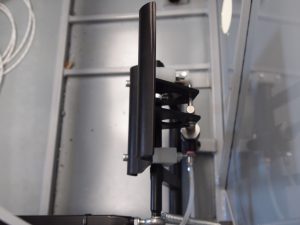
Installed rudder pedal looking from the top
Once all parts are ready for final assembly, lubricate the rotating and/or pivoting surfaces with a small amount of Thixo #2 Aviation grease and install with the proper hardware. There is no torque value for the bolts that secure the pedals and nylon blocks through the floor. The torque on these nuts should be such that the pedals are not clamped so tight in the nylon blocks that they are stiff and notchy, nor should they be so loose that they feel like the are flopping around. It is, however, important to ensure that all hardware is “in safety” by 1-3 threads past the nylon locking mechanism in the nut.
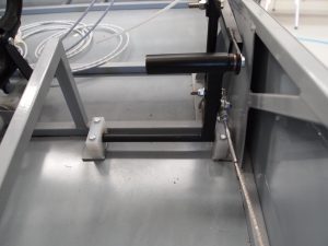
Rear rudder pedal installed, the 2 white nylon bushing blocks that the pedal pivots off are the ones that need bevelling on the front bottom edge.
When assembling our pedals, we couldn’t figure out where the two springs, that act as a centre return for the pedals, connect to. If you happen to be wondering the same thing, there are two special brackets that attach to the bottom engine mount bolts that they connect to.
After this step is completed, the toe brakes can be fitted as per step 5.
Happy Building…
Recent Comments